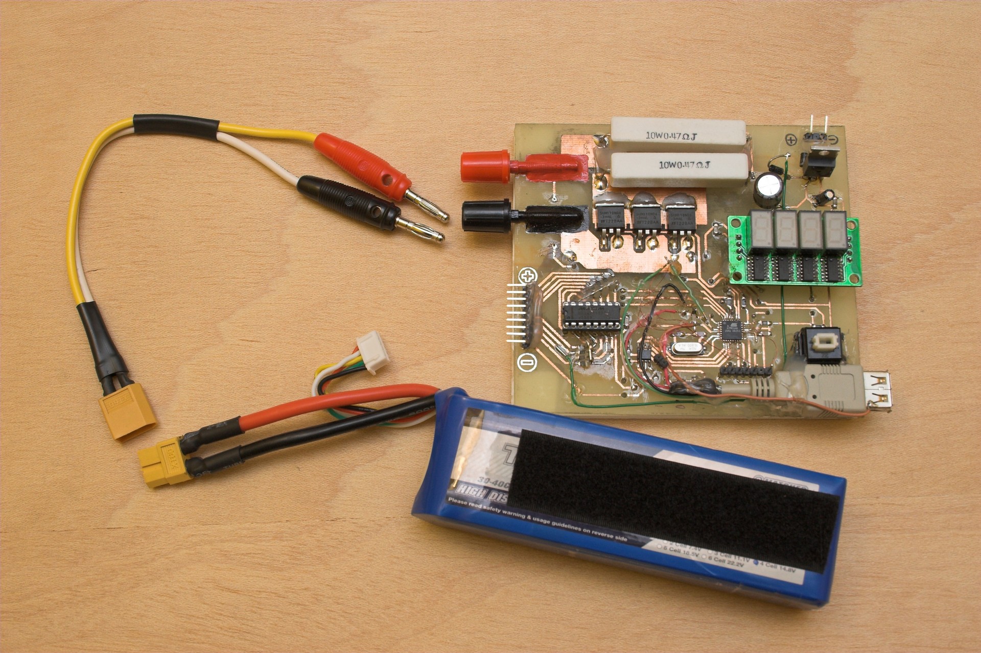
Multifunction Model Instrument
The below instrument can be used for the following measurements:
-LiPo Internal Resistance Meter
-Propeller rotation speed meter
-Battery current meter
The base of the instrument is the originally designed LiPo Internal Resistance meter. The other two
functions are realized by separate circuits that are connected to a USB socket mounted on the PCB that
supplies power and recieives signal from the other two instruments.
Further information: 
LiPo Internal Resistance Meter
Video of operation
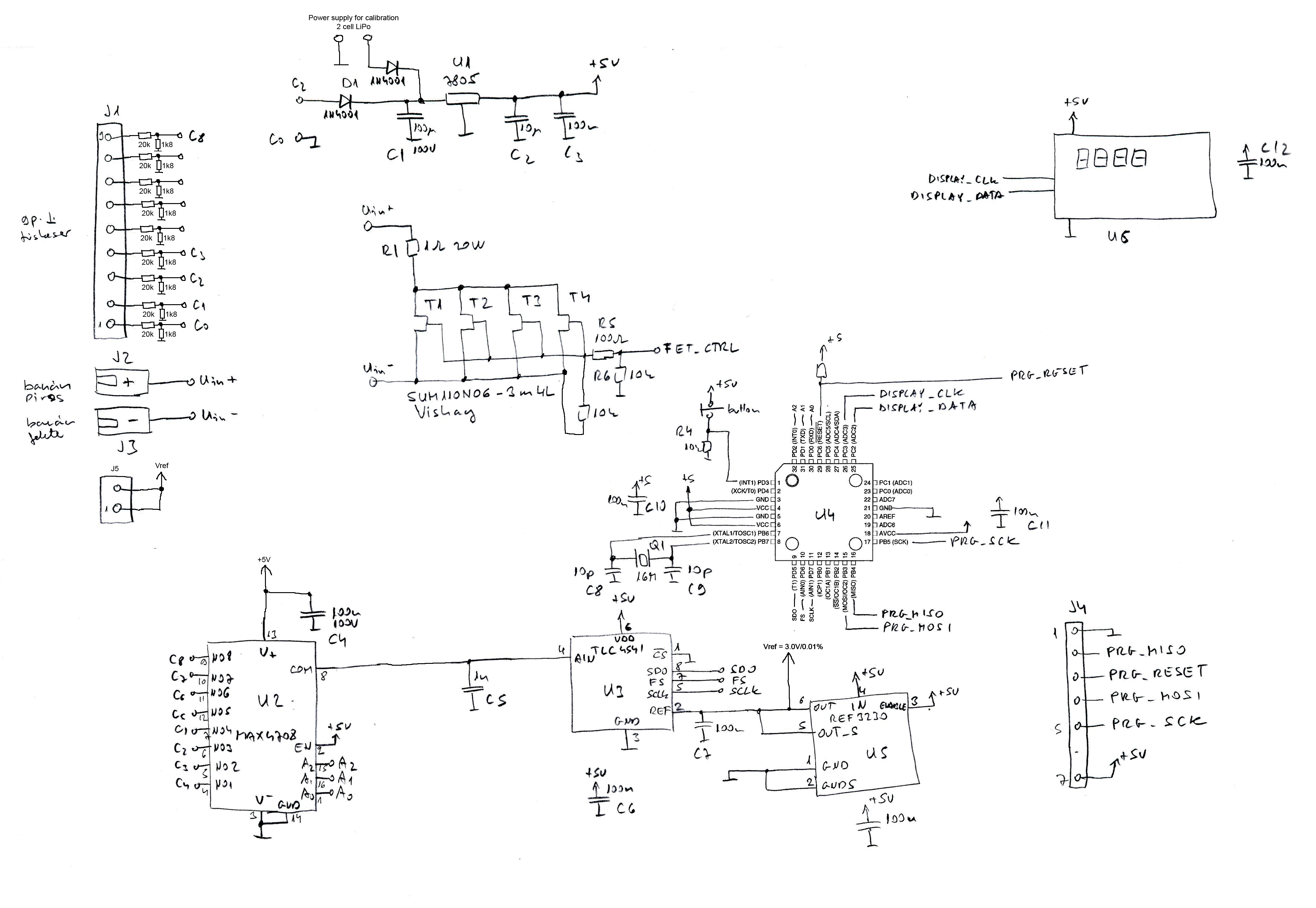
The below documents describe the first version of the pcb. The final design is modified. Please check the schematic for correct PCB modifications.
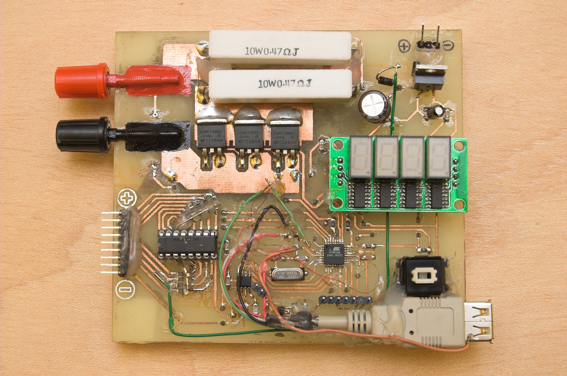
PCB top routing layer
Component position drawing on PCB
PCB jumpers on the bottom layer
The below program code is for operating all the three instruments.
Program code in C for Atmel ATMega 8 microcontroller
This device can be used to measure the internal
resistance of Lithium Polymer batteries used in electric RC models. The power
consumption of these models is quite high, and the batteries wear out in
100-200 recharge cycle. The internal resistance is a good measurement of the
age of the batteries. New cells are below 5mohm, and the ones at the end of
their life are above 20mohms. It also depends on the original quality.
The only problem is that I don't know how the internal
resistance is defined, so I made my own definition, and I measure that: The
battery is fully charged, cell voltage is about 4.2V. The unloaded cell voltage
is measured. Than it is loaded with 1ohm for 2.5ms, and the loaded cell voltage
is measured. The load current depends on the number of cells (N*4.2V/1ohm) and
the time of loading. I experienced that the voltage falls immediately to a low
value, than rises again in about 100us. Than falls exponentially to a lowest
value in about 2.5ms. Than it remains constant for long enough time to measure
all the cells.
In case of a 8 cell battery the voltage is about
33.6V, the load current is 33.6A so the 20W resistor is loaded by 1130W.
Specifications
- 2-8 cell LiPo battery, (tested up to 4 cells)
- Accuracy of voltage measurement: estimated 1%
- Accuracy of Rin measurement: estimated 6% due to the accuracy of the load resistance and the RDSon of the FETs.
- Load time: 2.5ms + Ncells*110us
- ADC resolution: 16bit
Operation
1. Connect the battery balance connector to J1, main current connector to J2 and J3.
2. When the controller boots up "CSEb" appears on the display for 2 seconds
3. The following is looped on the display:
"rin" = Internal resistance mode
"rPM" = Propeller speed mode
"Curr" = battery current mode
Press the button when the required mode is displayed. In this case: "rin"
4. Now the following is looped on the display:
"C= (number of cells)"
"ALL=(unloaded total voltage [V])"
"C(n)=(unloaded voltage of cell n[V])"
Press the button.
5. The following is looped on the display:
"Curr
"r
Self
calibration
For calibration an accurate 19.0V voltage source will be used
that can supply about 500mA current.
1. Connect all the pins of J1 to the 19.0V source while pressing the button
2. "CAL" is displayed for 1 second
3. "dOnE" is displayed when calibration is finished
Known
problems
- Although the calibration is done at about 2/3 full scale there is about 1% inaccurancy
at some voltages.
- The PCB is hacked since the last pdf-print!
Propeller Rotation Speed Meter

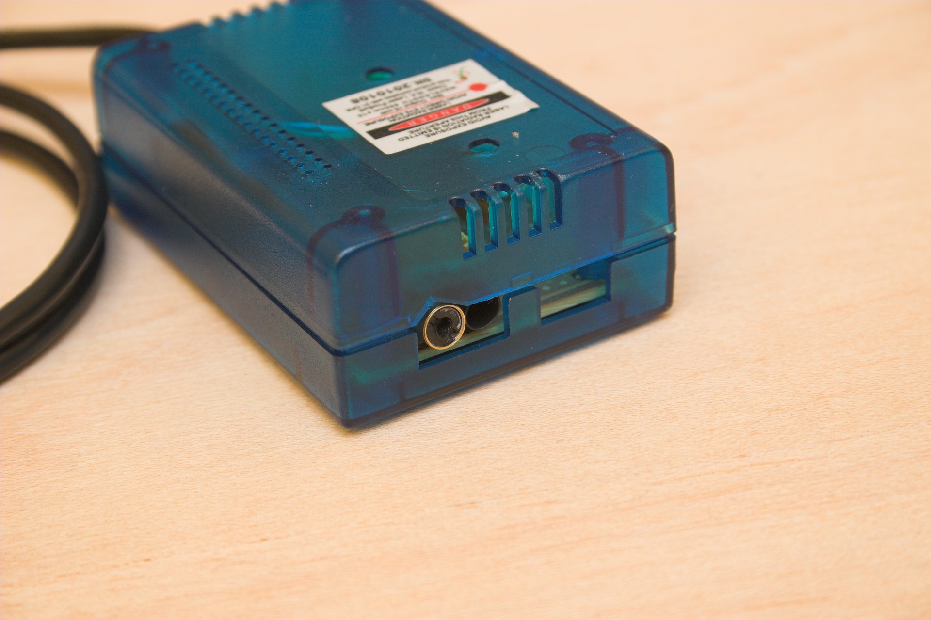
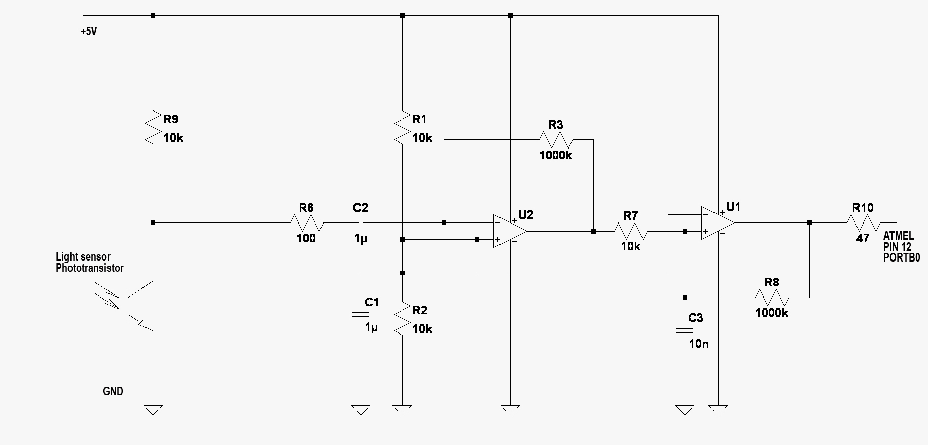
The measurement is based on the light intensity changes when the propeller blade passes
in front of the sensor. It does not matter that the blade shades the light, or
reflects it into the sensor, the change is detected anyway. If the display does not show a consistent
value try to change the way of light to make bigger contrast.
Use the point of the laser that can be seen on the rotating propeller to avoid touching the
blades with the instrument.
Specifications
- Blade number range: 1-8
- RPM range: 68/(number of blades) - 100000
Operation
1. Connect the battery balance connector to J1
2. When the controller boots up "CSEb" appears on the display for 2 seconds
3. The following is looped on the display:
"rin" = Internal resistance mode
"rPM" = Propeller speed mode
"Curr" = battery current mode
Press the button when the required mode is displayed. In this case: "rPM"
4. The actual number of blades is displayed. Press the button until the desired number of blades is displayed,
or wait about 2 seconds or until the sensor senses the first light change.
5. The actual rpm is displayed in 10rpm unit
6. Anytime you press the button you get back to point 4.
Battery Current Meter
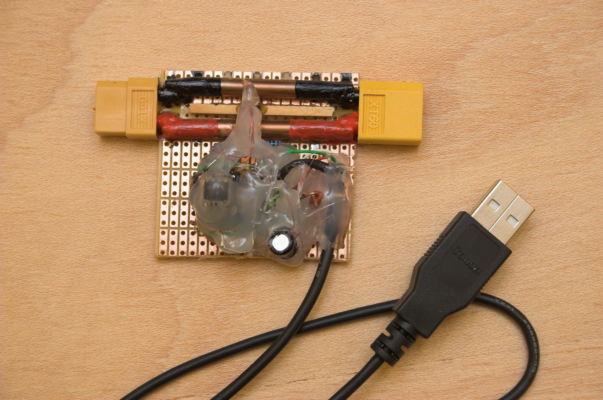
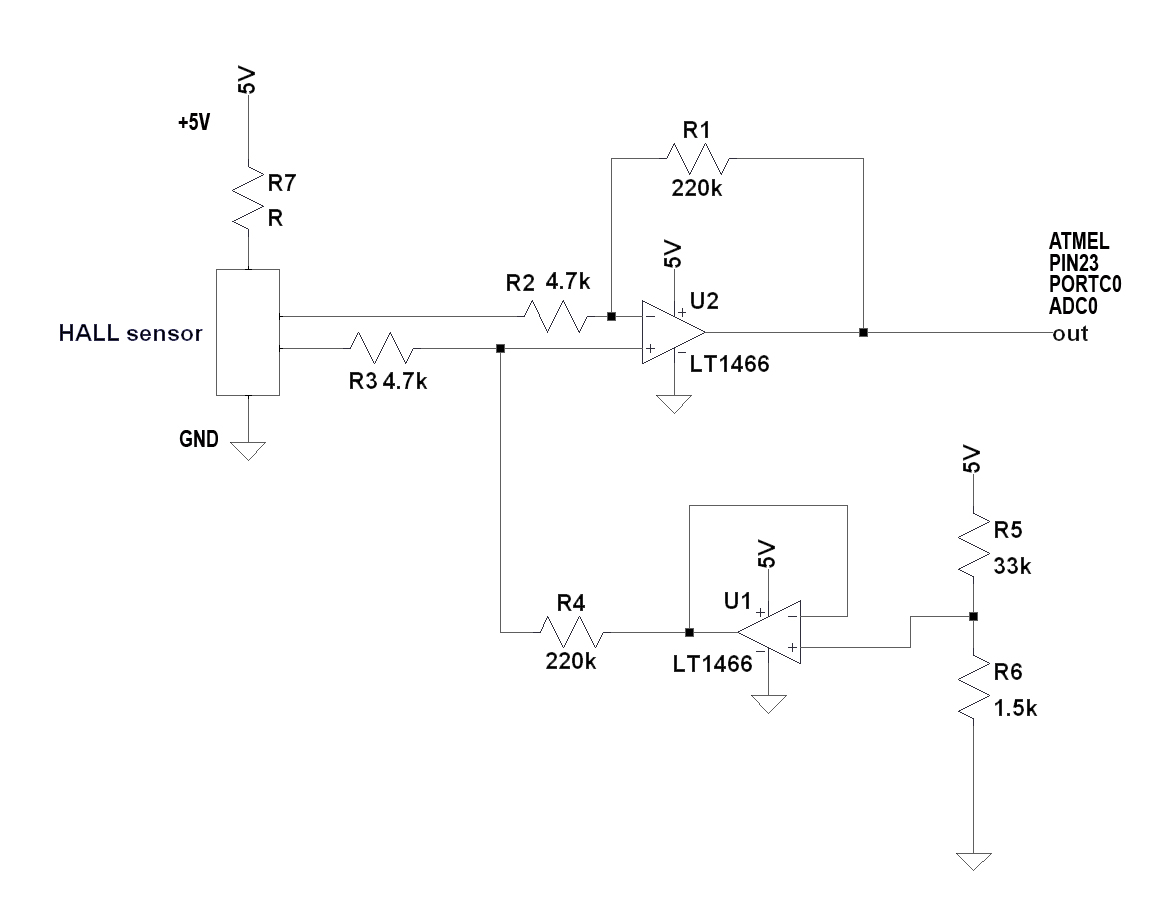
A hall efect sensor (disassembled from a floppy drive) is placed between the negative
and positive current conductor. The signal of the sensor is amplified.
A simple shunt resistor can also be used, and that gives a precalibrated current signal.
The signal of the hall sensor depends mainly on the relative placement of the tensor and
the current conductors. The advantage of the hall sensor is that it can not be overloaded.
The hall sensor is sensitive to the magnetic field of the Earth. While in the measurement
do not move the sensor.
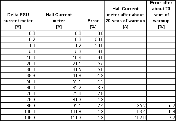
This version is caplibrated to a 110A bench power supply.
Specifications
- Measurement range: approx. 170A
- Accurancy: see calibration table
Operation
1. Connect the current sensor between the battery and the ESC.
Place it at the position where it will reside during the measurement.
2. Connect the balance connector of ANOTHER battery to J1
The instrument calibrates the offset caused by the Earth magnetic field.
3. When the controller boots up "CSEb" appears on the display for 2 seconds
4. The following is looped on the display:
"rin" = Internal resistance mode
"rPM" = Propeller speed mode
"Curr" = battery current mode
Press the button when the required mode is displayed. In this case: "Curr"
5. The actual current is displayed in 0.1A unit
Measured calibration data